Ask Electronics

3288 readers
11 users here now

For questions about component-level electronic circuits, tools and equipment.

Rules

1: Be nice.

2: Be on-topic (eg: Electronic, not electrical).

3: No commercial stuff, buying, selling or valuations.

4: Be safe.


founded 1 year ago
MODERATORS
1


So i built a outdoor hoop antenna to replace my cheap and crapy walmart antenna. IDK if the pre-amp fried the 5g/LTE filter or it wad my diy antenna. Is it possible for a 5g/LTE filter to stop working and filter out every channel. I orderd a new filter to see if it is the problem. Here is the antenna tutorial I followed: https://youtu.be/Tg0JjeotXq4 And the 5g filter: https://a.co/d/gwpNo2g

2


I recently got a nice deal on a stereo microscope, and leapt at the chance. I've had a few projects in mind that would entail SMD soldering, and now all I need is a proper soldering station.

My current iron is pretty basic, but gets the job done for splicing wires and DIP work. Now I want something with temp control and a good supply of tips.

It seems like hobbyists are all talking about affordable Chinese T12 stations from brands like KSGER and Quecoo. There are just so many different models, it's hard to understand the features and differences. It also seems like there's a lot of "Reddit folk knowledge" where people just keep repeating what others have said. Eg: People say that some KSGER stations have no case grounding, but nobody says which models do or don't have the issue. All of them? Then people talk about the microcontrollers STM vs STC, but nobody says why it matters.

3


Back in my day, you could usually sip a few mA from a USB2 port without any trouble.

When I try that now, Windows pops up with a “device not recognized” error. I know you can draw up to 150mA before enumeration, but it looks like after some time, Windows will complain that you haven’t enumerated yet.

Is there an easy way to keep from getting this error without having to actually make the device smart?

I’m hoping for something dumb along the lines of USB-PD but facing the other direction. For the record, it has to work on a USB-A port, so USB-C hacks won’t work.

4


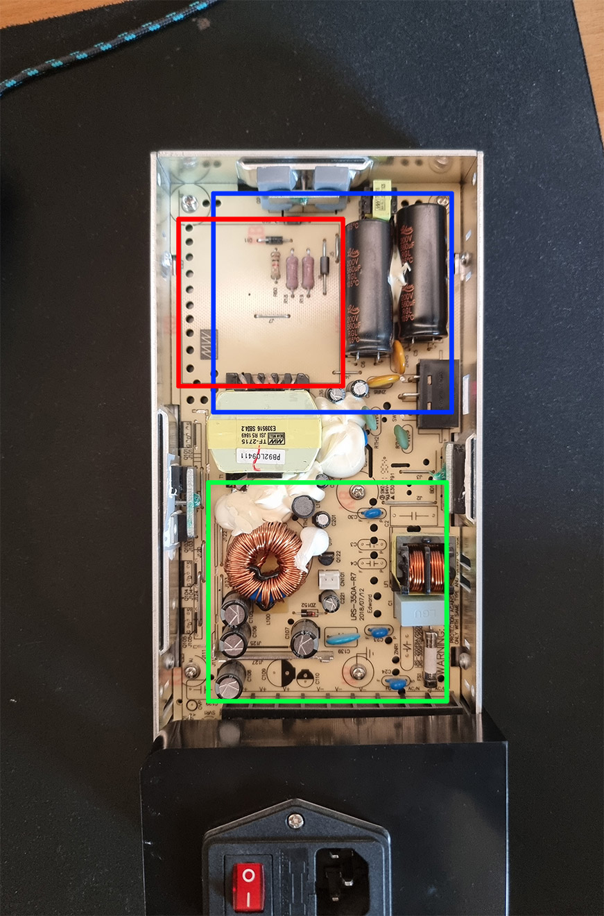
Hi, my 3d printer psu fan gave up the ghost, and I wanted to replace it. It was pretty noisy, so I thought about upgrading from a 30mm to an 80mm fan. I am designing the top case with mounting holes, and want some input on where to place the new fan. The original placement is the box with the red color. The green and blue box are some options I thought of for the new fan placement. Would placing it over the busier part of the pcb yield lower temps, or is that a bad idea? Does placement even matter for psu fans? The new fan has higher airflow, but lower static pressure than the original one, and the plan is for it to always spin at a low rpm and occasionally speed up when the psu detects a high temperature. The original config runs it completely fanless until the psu reaches 50c and only then does it send voltage to the fan header.

5


I have a 750m 0.75mm² wire on a spool that needs a quick disconnect connector of some sort on it so it can take it off in 250m lengths. But it has to handle the tension of being spooled up. Any ideas?

In an ideal world it would be a male and female banana plug thing, but that wouldn't hold under tension. So I'm hoping you folks have ideas.

6
7
submitted 2 weeks ago* (last edited 2 weeks ago) by mattreb@feddit.it to c/askelectronics@discuss.tchncs.de


Bought a new PC, and I was measuring its consumption out of curiosity. I noticed something weird (to me): when the PC is off (in fact, I completely disconnected the PSU and did the same test), there is quite some current running in the power cable to the PSU (0.15A).

Further measures showed a power factor of (almost) zero, and I can actually measure a capacity of 2uF across the PSU ac input.

I did the same thing on an older PC I have, and there is no current / capacity. So what would the reason of a capacitor across the mains on the input be in a PSU?

PS: the PSU is a Thermaltake Toughpower GF A3 1050W

Edit: I found some official measurements for this specific PSU: https://www.cybenetics.com/evaluations/psus/2249/ that have 40W standby apparent-power by design

7


I'm looking for a 5 pin connector type that I can easily find chassis plugs for both male and female.

I've looked at DIN and mini xlr connectors, but have unsurprisingly been unable to find male chassis sockets.

The pins needs to support 12V 10A*

*realistically only expects about 6-7A flowing through 1 pin and one fourth of that through the 4 others.

8


The electric PTO clutch on my 1969 mini tractor is dead and discontinued.

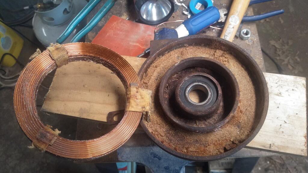
Original winding is aluminum 18 gauge. Manufacturer specs were 2.88ohms, 237 turns. The manufacturer specs didn't quite physically match what I found when I took apart the old clutch. If I understand this correctly, the 2.88ohms is the most important part and will pull 4.17 amps.

I just attempted a coil with 18 gauge copper magnet wire. I made it to the max dimensions I can get in the housing with a scramble wind. I'm getting 1.2 ohms, which would pull 10 amps or so. Not good.

Was able to get 187 feet given the resistance.

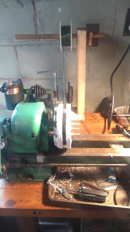
If I go with 20 gauge copper, assuming I can get 235 feet (1.26 * 187) and I should get 2.319 ohms. Probably get a little more than 235 feet and get the resistance up a little more.

What does this do to the strength of the magnetic field?

Would I be better off putting a power resistor in series with my 18 gauge coil?

Any advice greatly appreciated!

9


I'm working on a mod kit for a popular item, but my target audience isn't likely to have a soldering iron. The majority of the project connects to an exposed ribbon connector, but I need to short two terminals to force a power supply on.

Any ideas on a method I could provide for people who can't solder? Maybe a strip of copper tape?

10


Hello everyone, I bought a bottle dynamo for my bicycle with a rear and front light. Though I have one little tweak that I would like to add and that's a way to keep it light up for about 1 minute (at least 30 sec) without pedaling. I thought of putting a capacitor in the circuit to store some energy but I would like what do you all think of it ?

Thank you for your time and have a nice day you all !

11


Can I charge a 19V laptop from multiple USB ports?

My laptop's charger is rated at 19V 2.1A. I was wondering if it would be possible to build an adapter which would allow me to charge it from a power bank, even if just slowly or via multiple USB ports.

I know you can buy adapters which utilise USB power delivery, but most outlets and powerbanks don't have PD yet.

@askelectronics #AskFedi #Electronics #DIY #USB

12


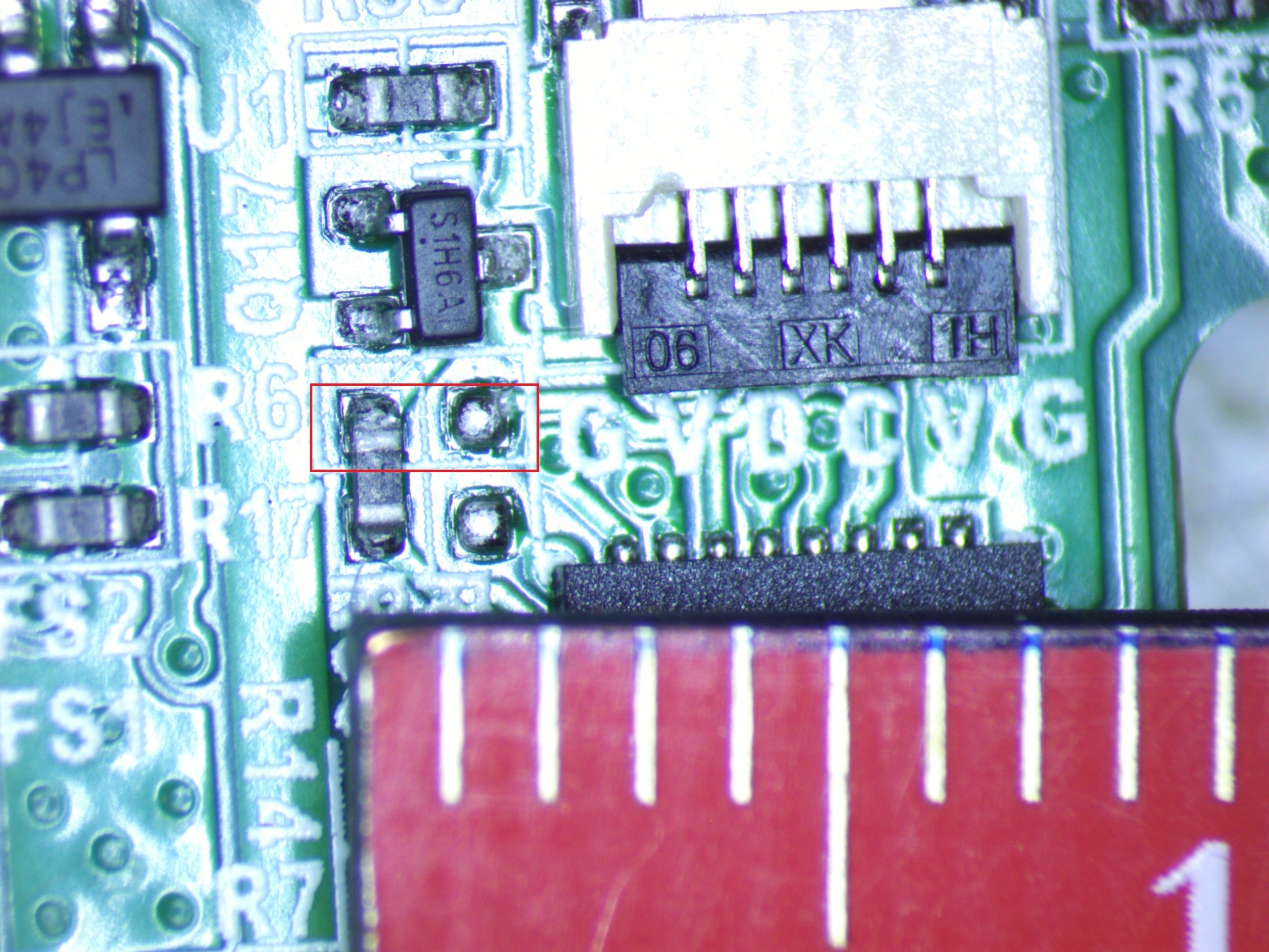
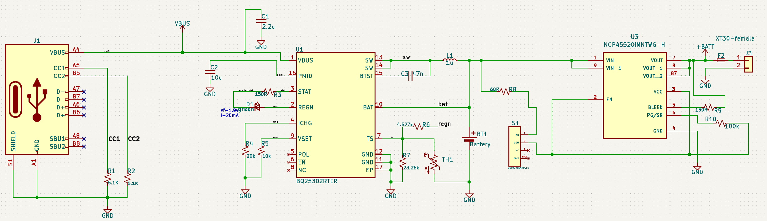
I've been messing around with circuits my entire life but this design was time sensitive and I've never done my own PCB designs before, so I hired someone to put this together. After getting some test boards, when I plug them in the charger chip gets very hot and smells like burning....

Circuit is just a simple li-ion usb charger and a switch. I've gone through the datasheet for the bq25302 more times than I can count and I'm missing something obvious here. Using it just for delivering power seems to work fine, the problem is only when charging.

I do see R6 + R7 off TS don't have the recommended 10k values, but I don't feel like that would cause what I'm seeing. This is being connected to a 21700 lipo.

Someone mind lending me their eyes please?

bq25302 datasheet - https://www.ti.com/lit/ds/symlink/bq25302.pdf

13


A simple thing like this, but premanufactured. I scoured the internet trying to find one (at a reasonable price) and there is nothing. I would make one myself, but I just don't have the time currently to do that.

I need it for a mains fan control. Doesn't have to be fancy (all of the ones I encoutered were very fancy, with touch sliders and whatnot), 5 steps is enough, on/off control as well as speed control through the remote. Nothing fancy, as I said, 5 steps is more than enough. So, basically, just 3 buttons on the remote: on/off, + and - is all I need.

Also, I don't need smart/phone/app solutions, I would like it to just have a remote, that's it.

14


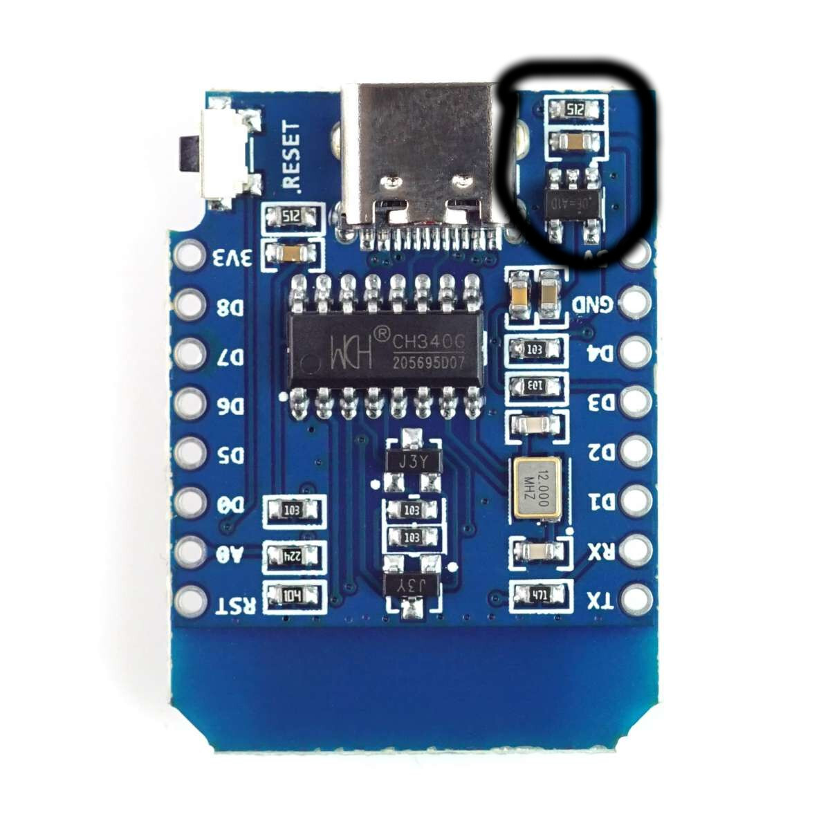
I asked a while ago, how to build an automatic light switch and finally got around to actually building it.

My board is an ESP8266 mini D, and ignoring all the sensor parts, my problem right now is powering the actual light.

It's just a small LED array and I connected it directly to the 5V and GND pins (controlled via a transistor).

Measuring from the wall (so including the PSU), this whole setup pulls about 3W (so far expected), however, one small component close to the USB connector gets uncomfortably warm, and I'm not sure, whether that's ok.

The hot component is one of the two small thingies circled in the picture. I thought the 5V get pulled directly from the USB plug, so I'm not sure, why there is any circuitry involved.

15


I've been trying to solve an automotive electronics problem for several weeks now, but everyone I've spoke to can't seem to come up with a solution.

In brief, I'm trying to add a relay in-line with the horn switch in my car, such that I can close my own circuit when the horn is pressed, without affecting the existing horn circuit in the car.

I had some JD1912 12V relays left over from a previous install, so I tried to use those. (Relevant image: Diagram)

First, I placed connected the trigger wire (pin 86) to the the wire coming into the horn switch, and the ground (pin 85). The relay triggered when the horn button was pressed as expected, but this also caused the actual car horn to sound continuously. Presumably doing this was enough to give the factory horn relay enough current to close.

Next, I tried placing the relay in series with the horn switch by splicing the wiring heading into the horn switch, and connecting the relay (pin 86 and 85) in line. Once again, the relay triggered with the horn switch as expected. However, this time, the actual car horn didn't sound at all.

The best I can work out is that there's a resistor in-line with the relay trigger (otherwise connecting it straight to ground would cause a short, right?) However, that resistor is just enough to allow the factory horn relay to trigger when connected to ground.

The way the car is designed, I can't splice into the wire coming out of the switch to detect when the horn is pressed, since it's a shared ground with other components.

My question is, is there such a thing as a relay with no resistor? Essentially all I'm looking for is a component that will "detect" current on the horn switch wire, and close a separate circuit. I'm not sure if a relay is even the correct way to go about this. Hopefully you guys can point me in the right direction.

16


cross-posted from: https://lemmy.dbzer0.com/post/26703241

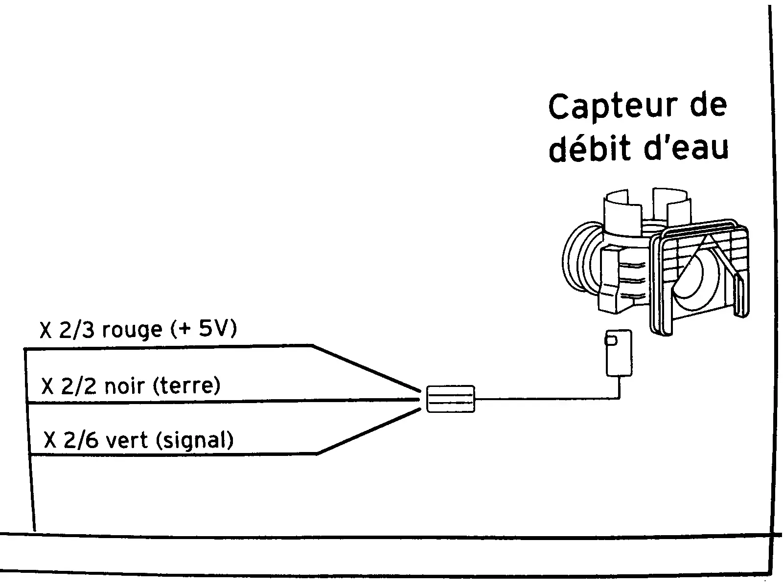
This diagram is from the service manual of a combi boiler. It’s a flow sensor which detects whether hot water is running, which is then used to trigger on-demand heat and switch a diverter to take radiators out of the loop.

In English, the diagram shows:

  • X ⅔ red wire (+5V)
  • X 2/2 black wire (ground)
  • X 2/6 green wire (signal)

I need to know what those fractions mean. I took the voltage measurements in this video:

I cannot necessarily trust the model in that video to have the same specs as mine. My voltmeter detected 4.68 V on the red input wire showing that the sensor is well fed. The green “signal” wire is supposed to be 0 V at rest and 2 V with water running (or I think the reverse of that is used in some models). In my case the green wire is ~1.33 V at rest and ~0.66 V when water is running. I need to know if these readings are normal as I troubleshoot this problem.

update


@unexposedhazard@discuss.tchncs.de and a couple others gave the answer I was after. Then @tofubl@discuss.tchncs.de helped solve the underlying problem. The theory that the sensor was fine but the board was not drove me to test the sensor in isolation. The sensor gave correct output in isolation. Then I connected it back to the motherboard to retest and reconfirm that it’s still broken. But it actually worked. The hot water suddenly and mysteriously works now. I guess the act of draining the water and unplugging the connector then reconnecting and repressurizing caused it to work. It may be temporary, since in the past it was hit or miss whether it would work.

17


I've recently been learning about superhet and frequency mixing and wanted to start tinkering. Specifically I'd like to try using two heterodynes in series to first frequency shift then uninvert the original audio, sort of like an analog frequency shifter.

To do this, I'd need a frequency mixer. I've been looking at a ring modulator (like https://upload.wikimedia.org/wikipedia/commons/1/1b/Diode_DBM.png) which should require 4 shottky diodes and 2 center-tapped transformers. I've had difficulty locating an affordable transformer, with good enough fidelity for audio, that also includes a center tap.

I have a few questions:

  • Where can I locate affordable, good-enough-for-audio transformers?
  • Is the ring mod approach good enough? I see there's also a gilbert cell.
  • Any general advice for someone just starting a project like this?

Thanks!

18


Hi there

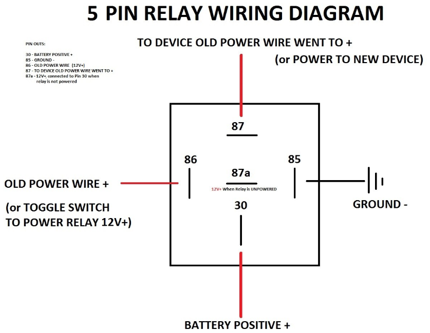
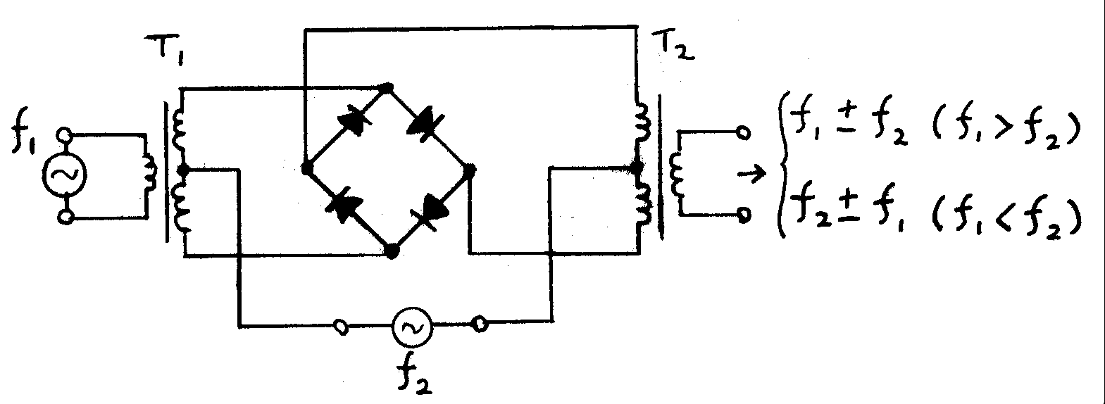
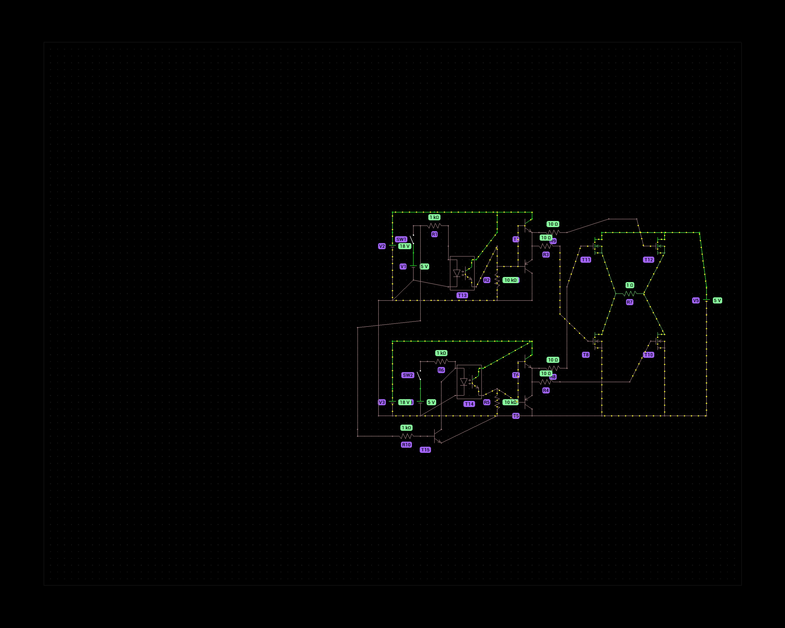
The purpose of this schematic is to control a DC motor that runs at 8V max. That is why I chose 4 N-channel mosfets in the H bridge. P-channels would not fully activate at voltages above -10Vgs but the N-channels can handle 18V at the gate.

The 5v switches represent an Arduino's digital output pins. One to turn forward, one for reverse. To prevent a failure scenario where both pins are HIGH I added a transistor that prevents current from flowing through the optocoupler on the second half bridge.

Does this circuit make sense? I'm not an electronics engineer, just a hobbyist and have doubts about how effective the gate driving circuit is of the mosfets.

Thanks!

19


I'm trying to build a very simple, stupid light switch for my grow light. Essentially, I want to turn on the light, if it gets too dark outside, so that my plants can survive the northern winter.

Since I'm a software guy, my first thought was an ESP32, but that seems excessive.

My current approach would be something like this: https://www.ebay.com/itm/313561010352 In conjunction with a relay, both powered by a USB-PSU.

If the light level is low enough, the logic DO pin should send a signal and that should be enough to trigger a small relay, so that the relay then closes the circuit to switch on the lights.

Is that idea completely stupid? With electronics, I'm usually missing something very obvious.

The lights themselves are already just usb powered and only draw 5W, so that shouldn't be problem.

What I'm concerned with is the actual switching. Is the logic signal "strong" enough to activate a relay? Would simple transistor maybe sufficient?

20


I have one of those basic motor kits you can buy off of Amazon. I was wondering what steps I should take to make it so that I can turn the motor on/off with the press of a button, wirelessly.

I'm still very new, so any information you can offer no matter how basic will probably be useful to me.

21


I've got a VFD display on board along with UPD16311 driver is made for negative voltage around -30V and i think so is display (i couldn't find any info on display) and I'm doing it mostly from junk parts. I want to know what devices could/should contain power supply for such voltage. I've tried -12V from psu i've got lying around but it didn't work. There's also a chance that display itself is damaged but there's no visual sign of it.

22


According to the A4998 datasheet you're supposed to wait 1 millisecond after waking from sleep to allow the circuit to energise.

What is the worst that can happen if you neglect to do this? I use stepper motors to drive a plant watering pump and losing a step or two really isn't an issue. Is there a risk of damaging the module or is losing the first step the biggest risk?

I trigger the pump by pulling the EN pin low and a 555 timer on the STEP pin makes it pump continuously. It seems sensible to pull the SLP pin down as well with it as that saves a little bit of power.

23


I have a 3d printer in my car powered by a bluetti eb3a. The bluetti is charged by the 12v outlet in my car while driving. I have a 24v solar panel i want to mount to the roof of the car. My bluetti has only one dc 7909 input. So got a a Y splitter to combine power from the car and panel. But when plug it into the car outlet that turns off when i turn off the car, the solar panel turns on the stereo. Thats not the case with the outlets that are always on. I am worried that i will danage the car electrical system from a 24v solar panel flowing electricity back into the car?

24


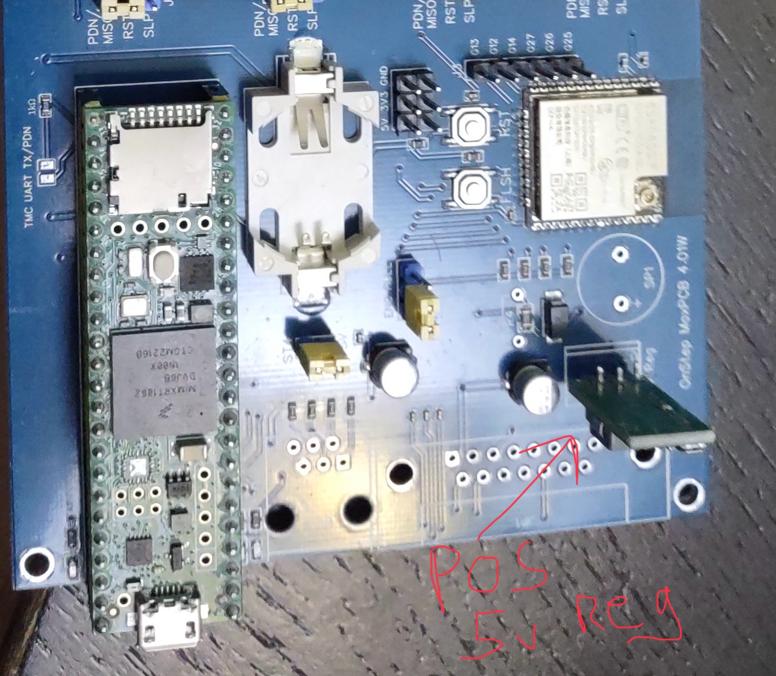
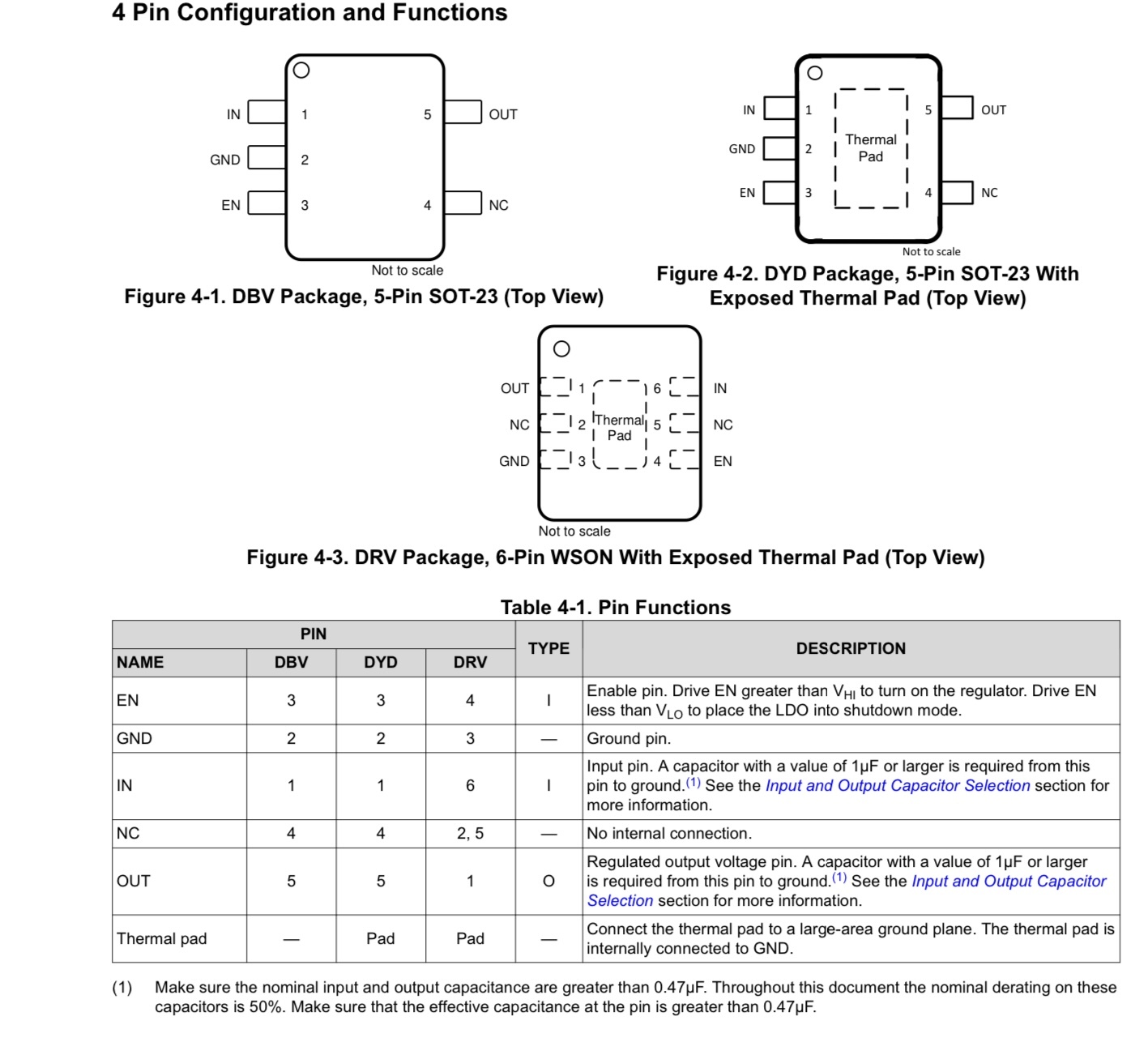
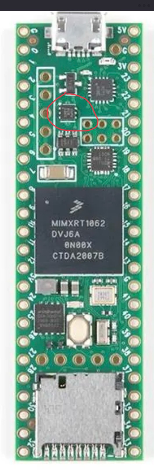
I have a project that is using a Teensy 4.1, the cheep 5v regulator I was using in the project let the magic smoke out for no good reason. I replaced that but now the Teensy boots and runs for about a min then quits. There is a TLV75733P power IC that is supplying the 3v3 and it gets hot then quits supplying power. Since that IC is $0.46 vs a new Teensy 4.1 ~ $40 I want to try and replace it. I have done a bit of SMD work but not tried to remove a tiny chip with a GND pad before so I’m looking for any tips. The PCB of the Teensy has header pins so I can’t really get good contact to a hot plate to preheat the board.

25
30
submitted 4 months ago* (last edited 4 months ago) by batvin123@reddthat.com to c/askelectronics@discuss.tchncs.de


I am working on a WLED project, using a esp32 in a 3d printed enclosere. But my dad says that i can't install it because it is not UL listed. He is worried if the house burns down, the insurance company won't insure it due to diy electronics possibly starting a fire. What am i to do, i am not developing a project to sell?

view more: next ›